Multiplexer to LEDs
FPGA Project 02
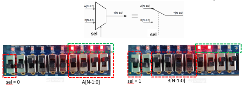
This FPGA project for beginners will help you implement a parameterizable 2:1 multiplexer. The inputs of the multiplexer are 2x Nbit buses that are driven to the output accordin to the sel bit (N>=1).
The mux output will light up the FPGA development board LEDs 💡 according to the board’s switches positions.
The Verilog code can be adapted to ther boards according to the number of switches/LEDs. It requires a board with a minimum of 3 switches and 1 LED.
Part 1 Verilog tutorial and Modelsim simulation
This practical Verilog tutorial for beginners will show you the following:
- How to design a synthesizable Verilog multiplexer with 2 input Nbit ports s (N=4 default) and 1 select bit. The mux output is connected with the LEDs on an FPGA development board
- How to create a Verilog testbench for the Multiplexer to LEDs project
- How to create a Modelsim project and to test your digital circuit modeled with Verilog
Part2 – FPGA programming with Intel Quartus Lite
This FPGA programming project for beginners will show you the following:
- How to create a Intel Quartus Project
- How to Synthesize a Verilog module
- How to connect your design to the FPGA pins
- How to program the FPGA and demo trial using the DE1-SoC Cyclone5 development board
I hope you enjoyed this Verilog FPGA tutorial 😊
If you want to see more Verilog FPGA tutorials subscribe to my YouTube Channel!