
What you’ll learn from this easy Verilog tutorial?
Project 1:
Design using Verilog a 4bit Gray encoder, a 4bit Gray decoder and simulate a testbench for them using Modelsim Intel FPGA Edition.
Project 2:
Design using Verilog a 4bit Gray counter, and simulate a testbench for it using Modelsim Intel FPGA Edition.
Note: You can download the Verilog design and testbench files at the end of the article.
Gray Codes Introduction
These binary codes were invented by Frank Gray and are now widely used to prevent spurious (glitchy) outputs from electromechanical switches, in error correction in digital communications systems or inside digital circuits for transmitting data between blocks that operate at different clock speeds (clock domain crossing). The codes are also called Reflected Binary codes and their special property is that two successive values differ only by 1bit. There is a very high chance that all the processors in the devices around you having this type of circuit inside because their internal blocks usually operate at different frequencies depending on their functionality.
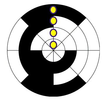
Let’s look at the rotary position encoder from the left. It has only 1bit changing under the yellow circles. This assures that only 1bit can be misinterpreted by a reading sensor when translating from one position to another. You can read a more detailed article here. To build a Nbit Gray code is quite easy and it starts from the Nbit-1 Gray values. Let’s make a simple example for a 3bit Gray code!
- We first need the 2bit Gray values: 00, 01, 11, 10
- Next create the reflected (mirrored) values: 10, 11, 01, 00
- Prefix old entries with 0: 000, 001, 011, 010
- Prefix new entries with 1: 110, 111, 101, 100
- Concatenate the two sets: 000, 001, 011, 010, 110, 111, 101, 100
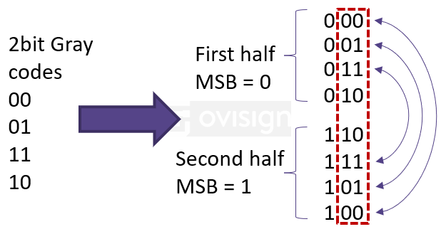
How to create 3bit Gray codes starting from 2bit Gray codes
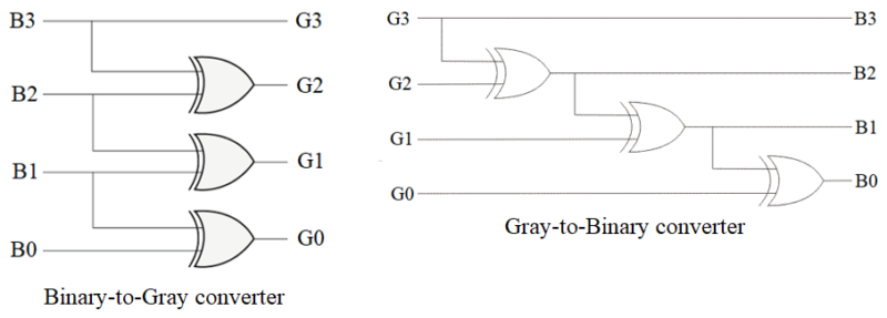
Gray-to-Binary and Binary-to-Gray converters are quite easy to implement in hardware. If you want to see a detailed explanation about how this circuit is created started from the truth table, I recommend this article.
4bit Binary-to-Gray and Gray-to-Binary converters
We’ll now focus on implementing a 4bit Binary-to-Gray a Gray-to-Binary converter using Verilog and Modelsim Intel FPGA Edition.
4bit Binary-to-Gray and Gray-to-Binary converters
Watch this simple, practical video and implement the Gray encoder / decoder and a testbench for them in no time!
Gray Counter
First In First Out (FIFO) modules are the most popular blocks used to pass data between clock domains that run at different frequencies. FIFOs have a data write and a data read port which need to communicate between them how much data there is to exchange and if the FIFO is full or empty. Gray counters are extremely useful here because a normal binary counter would create many transient (glitchy) states when the write / read pointers are passed from one clock domain to another. A normal binary counter has several bits changing between two consecutive states. If we consider the propagation delay of each bit, we can have a multitude of incorrect values of the write / read pointers that could be captured in the other clock domain. For Gray counters only one bit changes between two consecutive multi-bit values so a “wrong” binary value cannot propagate thus assuring reliable operation. Let’s implement a 4bit Gray counter and a testbench for it using Verilog and Modelsim Intel FPGA Edition!
I hope you have enjoyed this practical Verilog tutorial. If you’d like to receive more articles like this from me, I invite you joining Ovisign’s newsletter!

0 Comments