
This practical tutorial will show you how to perform simple Verilog write/read file operations and transfer data between testbench variables and Input / Output (IO) data files (it’s much easier than it sounds 😎).
Sometimes a Verilog design needs external stimulus – which is hard to generate inside a testbench, or the test scenario should be able to transfer read and write data outside the simulation environment. Some easy practical examples are:
- A program memory for a CPU used as input file
- Samples from an external sensor used for the module inputs
- Passing the output results of our Digital Signal Processing module to another file to allow spectral analysis in Matlab
- A list of expected values for the outputs
Verilog provides a set of standard system tasks and functions used for basic data reading and writing from and into files which allows you to:
- Open files, then read the values and assign them to a local testbench variable
- Open files, then write the values from a testbench variable to an external file
- Close files
Verilog standard write/read file operations
Working with files in Verilog is straightforward. The flow has 3 easy steps:
- Open the file ($fopen)
- Write or read data to / from the file ($fdisplay, $fmonitor, $fstrobe, $fwrite, $fread)
- Close the file ($fclose)
How to open and close files in Verilog
$fopen(“data_in.txt”) will return a 32bit unsigned integer called a Multi-channel descriptor (MCD) that has only one bit set to 1. If it was unsuccessful, it returns the value 0. Each $fopen will create a different MCD with a bit set to 1. You can open up to 30 MCDs because bit 0 is used by <stdout>, and bit 31 is reserved to 0.
$fclose(“data_in.txt”) will release the MCD value to be able to reuse it later in the testbench.

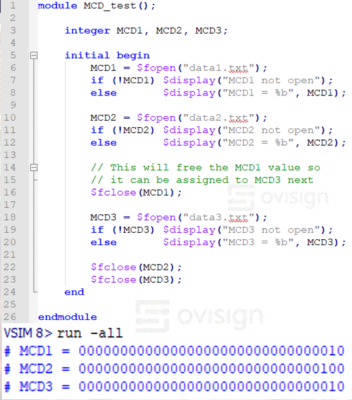 In this simple Verilog example, we can see how to declare three Multi-Channel Descriptors to open three files with them.
We can see in the console how MCD1 and MCD2 get the decimal 2 and 4 values after using $fopen. The $fclose from line 16 will release the MCD value for MCD1, making it available for MCD3. Because there are only 30 possible MCD values, it is important to manage how many are actively used.
Verilog File Output: Writing to files
You can write data into files using a set of simple system tasks equivalent to the console display tasks: $fdisplay, $fwrite, $fmonitor, and $fstrobe.
A task can be called using a formatted message $fdisplay(MCD1, ” Speed = %4d km/h”, speed); or simply by passing the variable to be printed $fdisplay(MCD1, speed); .
Each task prints decimal values by default or through a variant that can print to binary, octal or hexadecimal. For example $fdisplay offers $fdisplayb(), $fdisplayo(), and $fdisplayh(). Let’s do a practical example to master them!
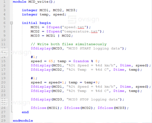 In this example, we are going to write the values of the temp and speed variables in speed.txt and temperature.txt. The test scenario is the following:
- First, we declare the MCDs, the speed and temp variables, then we open the two files to start writing them. We start by writing both files with a generic text by using MCD3. Pro tip: By OR-ing some MCDs you can edit multiple files at the same time with the same text
- Next, we change the values of the speed and temp variables and we print them separately in each file. After 1 time unit we change the values of the variables and print them again
- In the end we write another generic message with MCD3 in both files and close all MCDs
You should get the following output results in speed.txt and temperature.txt:

Verilog File Input: Reading from files
If you want to read data from a file in Verilog, you can use the system tasks $readmemb or $readmemh. These tasks will get the data from the file (binary or hexadecimal) and pass it to a 1-D array of reg type vector. The syntax is intuitive as the task needs the input data file name, the destination vector, and optionally the start / stop address of the destination vector. Let’s analyze these by doing some quick examples!
 First, create two files called data_in.bin and data_in.hex with the following content. Note that the files must be created at the same level where your simulator project is created (Modelsim in my case).
Next, you will create a Verilog file called file_read.v .
The test scenario is the following:
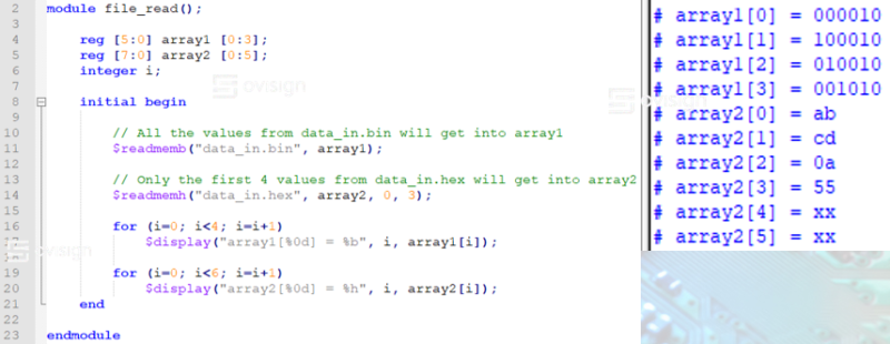
- We first declare two arrays that fit the bit width and depth of the binary values from the data_in files
- At line 11, we use $readmemb to fill array1 with the binary patterns from data_in.bin
- At line 14, we use $readmemh to fill the positions 0 to 3 with the HEX values from data_in.hex. Since the depth of array2 is 6, but we only load the first 4, array2[4:5] should remain noninitialized thus having the values 8’hXX
- At line 16, we use two Verilog for loops to print the contents of the 1D arrays, and the simulator shows the values are the same as those from data_in files
Verilog File Input Data Format
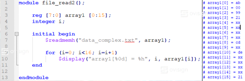
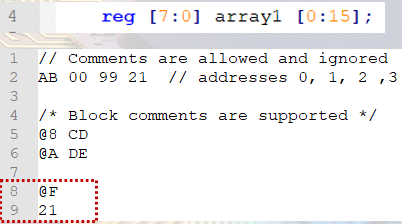 Let’s analyze a more complex data.txt format supported to load array1 using the command $readmemh(“data.txt”, array1):
- Inline comments, empty lines and block comments are ignored
- Line 2 is used to load addresses 0, 1, 2, and 3 with the HEX data 0xAB, 0x00, 0x99, and 0x21. Data for multiple addresses can be written on the same line
- At line 5, we load array1[8] with 0xCD. The @ character is used to specify the start of an [address, data] pair. Since we skip directly from address 3 to address 8, all the array1[4:7] values will remain 8’hXX (noninitialized). Note that it is very important to write the address value in HEX
- Lines 8 and 9 show that a pair [address, value] can be written on multiple lines. Note: this may be misleading and it not good practice
To test the memory file from above, please make a new Verilog file called file_read2.v with the following content:
If you’d like to know more about advanced Verilog Enhanced C-Style file I/O methods, I recommend reading the article “Master Verilog Write/Read File operations – Part2” (work in progress).
I hope you enjoyed this practical Verilog tutorial. If you’d like to receive more articles like this, please join Ovisign’s newsletter or enter our Facebook community!
Want to easily master the basics of Verilog through practical examples?
Back in the day when I first started working with Hardware Description languages (Verilog and VHDL), I had tons of problems at every corner. The simulator wasn’t working, I didn’t know how to debug, I found it hard to understand how to translate from a digital circuit schematic to a Verilog code, and it was very hard to even write proper testbenches 😭😔… No wonder less than 2% of all engineers work in the Digital Semiconductors industry.
Luckily I didn’t quit, and after 20000h in Verilog/SystemVerilog for design and verification and a PhD in Electronics, I put together all the pieces of the puzzle I worked so hard to solve back in the days 😊. I created a 5h hands-on Verilog course that will save you hundreds of hours of trial-and-error and frustration so you can easily master Verilog HDL Fundamental for Digital Design and Functional Verification! 😎 Let’s go together in this adventure in the world of Digital Semiconductors and Verilog 🚀🚀🚀!

0 Comments